

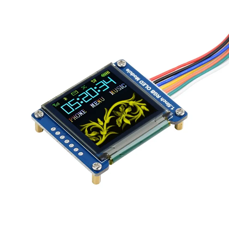
The display is available at Waveshare. It’s a 1.5inch RGB OLED Display that works over SPI and the 1351 driver. Before ordering this screen, I first confirmed that a driver is available in TinyGo.
Below are some specifications available on the product page. The prototyping is done using a Raspberry Pico. I’m using vscode on PopOS.
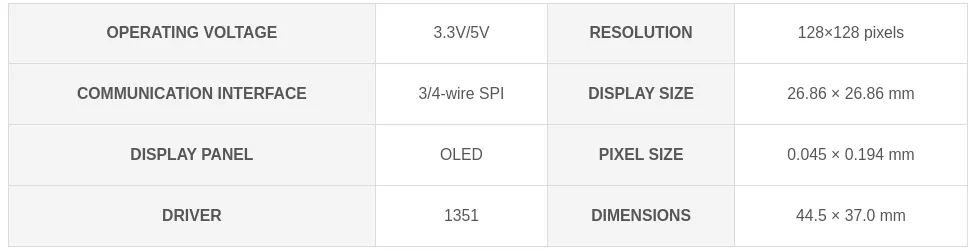
First steps with the display module
Prototyping is done on a simple breadboard. The display is the first thing I started working on.
Below is how I connected the display to the Pico. Note that all pins are arbitrary, it depends on what you define in the code.
The only exception is for the SPI, you need to use / declare the correct SPI pins with the associated display pin. This information can be found on the Pico pinout diagram.
Display | Pico (SPI0) | Description |
VCC | +3.3V | |
GND | GND | |
DIN | GP19 (or GP3 or GP7) | MOSI / SDA / TX |
CLK | GP18 (or GP2 or GP6) | clock signal (SCL / SCK / SCLK) |
CS | GP11 (or any other pin) | low→active |
DC | GP9 (or any other pin) | high→ data, low→command |
RST | GP10 (or any other pin) | low→active |
The hardware SPI of the Pico is used, in this case SPI0. I’ve used GP19 as MOSI and GP18 for the clock signal, but you can choose other pins as described in the Pico pinout.
First, SPI0 is configured. Mode 0 seems to work fine.
machine.SPI0.Configure(machine.SPIConfig{
SDO: machine.GP19,
SCK: machine.GP18,
Frequency: 40000000,
Mode: 0,
})
Go
복사
Then, the New() function creates a Display instance that will be used to interact with the display. This function takes 6 parameters, and returns a Device Display (I’ll use Display and not Device).
// New creates a new SSD1351 connection. The SPI wire must already be configured.
func New(bus drivers.SPI, resetPin, dcPin, csPin, enPin, rwPin machine.Pin) Device {
return Device{
bus: bus,
dcPin: dcPin,
resetPin: resetPin,
csPin: csPin,
enPin: enPin,
rwPin: rwPin,
}
}
Go
복사
The display is configured by default to use 4-wires SPI and I’ll stick to that.
You may have noticed the enPin and rwPin parameters in the function definition above. I don’t think these pins are necessary for SPI, and I can’t find what the enPin stands for. As for the rwPin, my guess is it’s a read / write select. Since these two pins are not available on my screen, I simply defined random GPIOs, in this case, GP4 and GP5.
display := ssd1351.New(machine.SPI0, machine.GP10, machine.GP9, machine.GP11, machine.GP4, machine.GP5)
display.Configure(ssd1351.Config{
Width: 128,
Height: 128,
})
Go
복사
The Configure() method implements the boot-up process available in the datasheet. As for the enPin and rwPin, they are configured as output pins by Configure().
I must not forget this in case I use these pins later for something else.
d.enPin.Configure(machine.PinConfig{Mode: machine.PinOutput})
d.rwPin.Configure(machine.PinConfig{Mode: machine.PinOutput})
Go
복사
The only time these two pins are used is to set rwPin low, and enPin high.
At this point, the display is working, with one major problem: the blue and green colors are inverted.
A[2]=0b, Color sequence: A -> B -> C [reset]
A[2]=1b, Color sequence is swapped: C -> B -> A
Plain Text
복사
The command 0xA2 is sent using the Tx() method provided by the Display instance.
display.Tx([]byte{1, 0, 1, 0, 0, 0, 1, 0}, true) // BGR -> RGB
Go
복사
We now have a working display! Time to move on to the next piece of hardware: the keyboard matrix.